DIY Eurorack Amplifier for Complete Beginners
For a long time, I thought electronics wasn’t for me: it was this arcane mixture of black magick and hardcore mathematics, in which everything has to be designed and assembled perfectly or nothing will work. Well, it turns out that’s not entirely true. It may be true if you’re building life-saving medical devices, or circuit boards for digital devices with high-speed signalling (like a PC or smartphone motherboard) where the actual physical length of connections matters, but not in the only kind of electronics that actually matters: DIY analogue audio gear.
Open that article, marvel at the squiggly lines in the picture, scroll until you start seeing equations, then close it again.
We won’t be doing that here. Where we’re going, we don’t need analysis. This is cargo cult electronics. And that’s OK. Because I reckon as long as you learn a few basic building blocks, and have an intuitive understanding of how they work, and the confidence & curiosity to try out different combinations, you can get pretty far. Just don’t start thinking you’re an expert.
This is part of my Memento Potato project, in which I am ostensibly producing my third album and releasing each track as & when it’s done, but also using it as a vehicle for tons of other things I’ve wanted to build/film/explain/code/nerd out about along the way.
Table of Contents
The End Goal
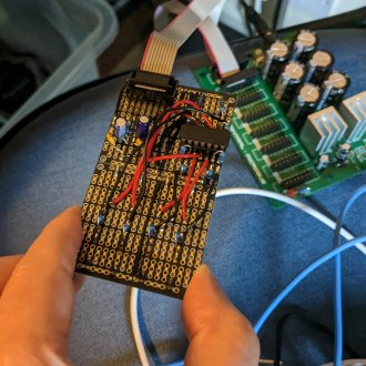
In this series of five articles - originally one, but it kind of got out of hand - we’re going to build this thing.
But by the time we get there, I want you to understand how it works. I want you to be able to look at individual bits of it and recognise what they do, and how they fit together, and that you could totally build a better one of these yourself by the time you get to the end.
One Problem, Four Types of Component
To illustrate my point, let’s take a simple problem, four component types arranged into two basic building blocks, and make a working, useful circuit.
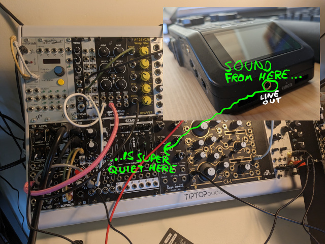
- Problem
- Plugging the audio out from a normal line out socket straight into my modular synth gives me really, really quiet sound
- Components
- Resistors
- Capacitors
- Diodes
- Op-amps
- Building blocks
- Eurorack power interface
- Non-inverting amplifier
Sure, there are a few other bits, like pin headers & jack sockets, but those are just fancy-looking wires: they have a specific shape, designed to let you plug in specific things (ribbon cables, patch cables, etc.), but electrically, all they do is make connections between bits of metal. If you really wanted to, you could make a pair of headphones that required you to solder three wires every time you wanted to plug them in.
The Series
If you already know what you’re doing, and just want to build the thing, go straight to The Final Circuit. Otherwise, follow along at your own pace.
- Introduction <– You are here
- Glossary of Jargon
- Powering a breadboard from 9V batteries
- Eurorack: Artisanal Jank
- Why is the audio too quiet, anyway?
- Eurorack sucks in all the best ways
- The Hyrdaulic Analogy
- High & low pass filters
- A “vintage” power filtering design
- Powering a breadboard from a Eurorack ribbon cable
- Op-amps for Noobs
- Open-loop comparators
- Buffers
- Voltage dividers
- Non-inverting amplifiers
- Rules of thumb for TL07xx op-amp chips
- 3.5mm mono jack sockets
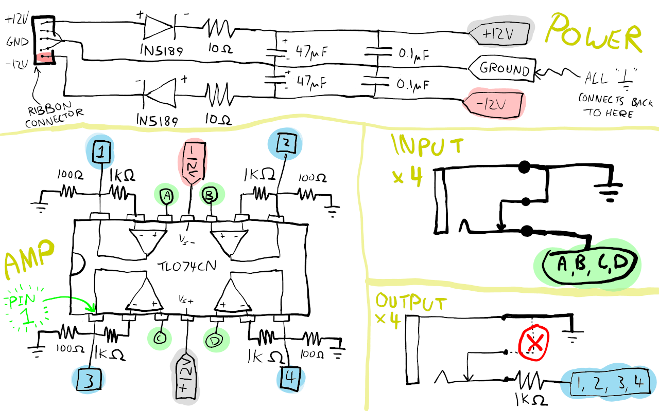
- The Final Circuit
- Recap
- Bill of materials
- Circuit diagram
- Building it on breadboard & prototype board
- Conclusion & calculators
To the Google Machine!
I’m going to assume a certain amount of knowledge about what a modular synth is, but try to make the fewest assumptions possible about electronics knowledge. Let’s pull some magic numbers off the Interwebs, and worry about explaining them later (if at all) - because that’s how I’m figuring this stuff out, and my whole point here is that you can do the same.
Electricity; an Illustrated, Incomplete, Inalphabetic Glossary
This is basic stuff. You probably already know it, but maybe not, and in any case a refresher can’t hurt. I am mainly writing this bit for myself, to try and get things straight and remember them. (Also to mess around with the graphics tablet I just bought.)
- V is for volts, named for Alessandro Volta. A measure of
electric potential energy: it only really has meaning when comparing two
things, and it has to have somewhere to go for that energy to do useful work.
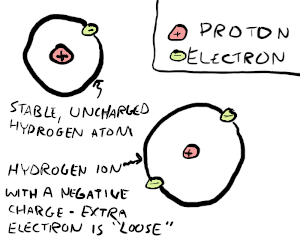
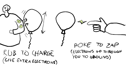
- Atoms in materials have a default stable state, in which they typically have the same number of electrons and protons. A material is negatively charged if it has more electrons than normal; those electrons won’t be bound to any specific atom, and can move around. Conversely, it’s positively charged if it has fewer electrons than normal: the protons in atoms with a deficit will attract unbound electrons.
- We can put a number on how much negative energy we transfer to a balloon by rubbing it on a jumper (giving it extra electrons), but it isn’t particularly useful to try and count how many electrons the balloon or jumper have in their uncharged, resting states. (Nobody designs circuits with one specific battery in mind, knowing how much charge that battery contains; they design them to work with any battery that, when fully charged, has a 9V potential difference between its terminals. Also, imagine trying to answer how many electrons there are in a socket connected to the mains.)
- After being charged, the balloon will happily sit there doing balloon stuff, until you bring it near something with less charge, like someone’s hair or a fingertip.
- If it’s always relative, how can we have a “9V battery”? 9 volts compared to what? Well, batteries always have two terminals, so a rating like this tells you there’s a 9V difference in charge between the positive and negative terminal.
- A is for amps, named for André-Marie Ampère. A
measure of current, or the rate at which charge is moving.
- That balloon we rubbed? As long as it isn’t touching anything, no charge is moving, so current is 0A. Then you poke it and get shocked: current went above 0A briefly - specifically, for as long as it took for the voltage between the balloon and your finger (their potential difference) to drop back to 0V.
- Ground is a bit of an overloaded term. The below may not be entirely
correct, and is almost certainly incomplete, but I’ll try and disambiguate
the uses I am aware of.
- If you just have a single, two-terminal power supply - a positive and
a negative, or even just a positive and something marked “ground” - and no
high voltages, metal enclosures, or anything else fancy, then “ground” is
just shorthand for “go back to the negative terminal”. You often see the
symbol used instead of explicitly drawing the wire for the return path.
This is just plain-old ground, or common ground.
- A toy circuit like a 9V battery, LED, and resistor might be drawn with the positive leg of the LED connected to the positive terminal, and the negative leg connected to ground. A bit lazy not to just draw the wire going back to the other battery terminal in this case, but that’s all it means.
- Because voltage is always measured between two things, there is also no
fixed concept of 0V. But in a circuit with positive and negative supply
terminals, if you know the voltage generated between them, it
makes sense to define 0V as the half way point, and measure relative to
that. This is signal ground.
- When making a circuit like this on a breadboard, it’s common to use two 9V batteries connected end to end: the positive end of one is the +9V supply, the negative end of the other is the -9V supply, and the point in the middle where they touch is your signal ground.
- When dealing with high voltages and/or electronics in metal enclosures,
you’ll also see earth, chassis, or protective ground.
- So called because the Earth itself, the literal ground, is a pretty convenient, near-infinite source or sink for charge: you can pump electrons into it or draw electrons out of it at will without filling it up or running out.
- This is not “free energy”; for that charge to do work, it needs some impetus to move. Think of a hydroelectric dam: lakes don’t just magically radiate free electricity, but allow a raised body of water to fall under gravity, and you can use that motion to drive a turbine. To pull electrons from the ground you need something charged to hook it up to, in the same way as the water has to be raised up against gravity before it can fall.
- Mains sockets & power supplies for these sort of circumstances will have a dedicated earth pin, electrically connected to any exposed bits of metal that might otherwise build up charge and zap you when touching, say, the side of your microwave. Somewhere there’ll be a literal metal rod driven into the earth.
- Also a verb: to “ground” something means to return it to its uncharged state, removing excess electrons (negative charge) or resupplying an electron deficit (positive charge) to its atoms such that they return to their normal, default state.
- If you just have a single, two-terminal power supply - a positive and
a negative, or even just a positive and something marked “ground” - and no
high voltages, metal enclosures, or anything else fancy, then “ground” is
just shorthand for “go back to the negative terminal”. You often see the
symbol used instead of explicitly drawing the wire for the return path.
This is just plain-old ground, or common ground.
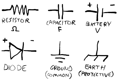
- Resistors resist the flow of current; not blocking it entirely, but limiting it.
- Capacitors store a certain amount of charge.
- Diodes only allow current to flow in one direction.
- Ω is for ohms, after Georg Ohm. A measure of resistance, i.e.
the degree to which a material impedes the flow of charge through it. The
higher it is, the harder electrons find it to travel, reducing current.
- Often written out, or omitted entirely, in favour of just using SI prefixes as a kind of shorthand: a “10k resistor” means 10 kilo-ohms, or 10000 ohms.
- F is for farads, after Michael Faraday.
This measures the ability of a thing to store electrical charge.
- It is distinct from C for coulombs, after Charles-Augustin de Coulomb, which directly measures an amount of charge, in the literal sense that you can directly relate it to numbers of electrons.
- Capacitors are measured in farads rather than coulombs because charge is compressible: if you think of voltage as pressure, charge as clothes, and a capacitor as a suitcase, then capacitors store more charge at higher voltages, in the same way you can jam more into your suitcase by sitting on it.
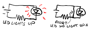
- A short circuit or short. Elecricity will travel the path of least
resistance. If you take a circuit where the only path between the terminals of
the power supply goes through a bunch of components, it’ll flow through those
components; if you accidentally touch a wire directly from one part of the
circuit to another that bypasses a bunch of components - giving the electrons
a shortcut, if you will - those components won’t get power.
- Also a verb: to short something is to temporarily create a low resistance path between two points; for example, making a high-voltage capacitor safe to handle by shorting it to ground, discharging it.
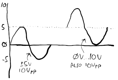
- The ± symbol means “plus or minus”. A ±5V signal means charge may flow both backwards and forwards, maxing out at 5 volts above ground in one direction, 5 volts below it in the other.
- Vpp means voltage peak-to-peak. A ±5V signal could also be referred to
aso 10Vpp, because there is a difference of 10 volts between the highest and
lowest points.
- Finally, a rail is just a fancy word for a thing that links a whole bunch of connectors together, or supplies raw power intended for multiple destinations.
Battery-Powering a Breadboard with +9V, -9V, and Ground Rails
Using our new-found powers - specifically, the knowledge that voltage is always measured between two points, and 0V/ground is relative - we can create a very simple ±9V power supply for a breadboard by simply wiring two 9V batteries in series, and deciding that the mid point between the two - where the left battery’s negative terminal is wired to the right battery’s positive terminal - will be our ground. As long as they aren’t going flat, the actual number of unspent electrons hovering around inside each battery doesn’t matter; as long as there is 9V difference in potential energy between the terminals of each battery, the maths all works out.
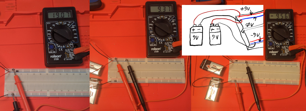
I actually measured 19V between the positive and negative rails here; clearly these particular batteries are putting out slightly higher voltages than they should be, but for experimenting & illustrating the point, this is fine.
Why is the audio quiet in the first place?
Well, it turns out that Eurorack uses audio signals anywhere between ±5V and ±10V, depending on who you ask. Jack sockets on “normal” audio kit, on the other hand, will be somewhere between ±0.447V and ±1.736V. (To clarify: I’m talking about “line out” sockets here, not headphone sockets. These use the same connectors, but trying to look up voltage levels for a headphone socket gets me no straight answer, but hints that the answer is much more nuanced, so let’s just forget about that.)
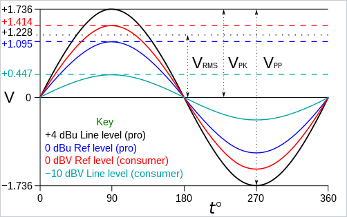
(Image credit AlanM1; used under CC BY-SA 3.0 / SVG exported to PNG.)
To Be Continued
Part 2 - Eurorack: Artisanal Jank