DIY Euro-amp Part 4 - Op-amps for Noobs
This article is part of my series on building a Eurorack audio amplifier, to go from line-out on a field recorder or Raspberry Pi to my modular synth rack. To start from the beginning, click here.
This is part of my Memento Potato project, in which I am ostensibly producing my third album and releasing each track as & when it’s done, but also using it as a vehicle for tons of other things I’ve wanted to build/film/explain/code/nerd out about along the way.
Table of Contents
Operational Amplifiers
To recap: we know why our line-out audio is so quiet when piped into the rack, we’ve reconciled ourselves to the jank of Eurorack on the basis that it is artisanal jank that makes it incredibly DIY friendly, and we’ve used the hydraulic analogy to build a practical power interface between the rack and a breadboard; one that is robust enough for our purposes against whatever other modules nearby are doing to the power rails and won’t blow up if we attach it backwards. But we still haven’t done anything about actually boosting our audio levels.
For that, we’ll need the fourth of the four component types I listed in the intro: operational amplifiers, or op-amps for short. I won’t go into how an op-amp works - partly because I don’t actually know myself; partly because this article series is already too large and has taken too long to write, so I have to draw the line somewhere - but will cover what they do, and how we can coerce their behaviour into something useful & controllable.
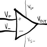
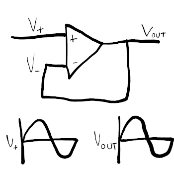
Op-amps have two inputs - the inverting input (V-), and the non-inverting input (V+) - and a single output (Vout), that outputs the difference between the two, multiplied by a very large number.
They are an active component, in contrast to resistors, capacitors, and diodes, which are all passive components: this means that in order to work, they need a power supply separate from the input signal, shown here by Vs+ and Vs-. These last two wires are often not shown on circuit diagrams, which confused me greatly to begin with. In the real world, they typically come packaged in the form of chips containing multiple op-amps, all driven from the same two power pins; so in diagrams, the power pins are either just assumed from context (if the circuit has a ±12V power supply, then unless explicitly mentioned, it’s most likely hooked up so Vs+ = +12V and Vs- = -12V), or a block representing the actual chip itself will be drawn on a separate diagram showing just the power pins, leaving the “functional” diagram to only worry about the inputs, outputs, and labelling which physical chip each op-amp comes from.
Open-loop Comparator
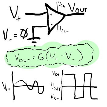
I digress. Getting back to the matter at hand: the output is the difference between the inputs, multiplied by something large. Vout = G(V+ - V-), where G is, for all practical purposes, basically infinite. Large enough that if you just keep V- stuck at zero, then for any V+ above zero, Vout will be some large positive voltage (in reality, limited by the type of op-amp, and not bigger than the supply voltage Vs+); and for any V+ below zero, Vout will be some large negative voltage. You won’t realistically be able to exert fine control over Vout by varying V+, because G is so big, that you would need to vary it by infeasibly teeny tiny increments. Forget about even trying. A hypothetical perfect op-amp that can swing its output fully from Vs+ to Vs- would basically give us a sine-wave to square-wave converter that ignores input volume:
From Comparator to Buffer: Feedback
That doesn’t sound all that useful to us, does it? We want something that can output an amplified copy of an input signal, but all we have is something that will compare the signal to zero and flip between high and low voltages. How do we bring this thing under control? The trick, dear reader, lies in feedback: by feeding the op-amp’s output back into itself, we can generate a Vout that mimics Vin.
- Our equation - Vout = G(V+ - V-) - only really works for the non-feedback case shown above. Introducing a feedback loop as shown below makes things really interesting, because it actually becomes Vout = G(V+ - Vout).
- Because of the loop, V+, V-, and Vout always change together. Instead of the
output just slamming between the rails, the behaviour becomes:
- When V+ is higher than V-, Vout (and hence future V-) will go up
- When V+ is lower than V-, Vout (and hence future V-) will go down
- When V+ = V-, Vout stops changing
- Effectively, the op-amp “wants” to satisfy V+ = V- = Vout, and will swing Vout as necessary to make that true.
- We call this negative feedback because we’re feeding the output back into the op-amp’s inverting input.
So now we have a circuit that produces an exact copy of V+ on Vout! How is this any more useful than just, you know, a plain old piece of wire? Well:
- The power for the output signal is coming from the op-amp’s power supply, not the input signal. Op-amps consume very little current on their inputs, and can supply relatively large currents on their outputs; so if you want an entire power-hungry analogue circuit in a Eurorack module, but don’t want to try and power the whole thing by drawing current from whatever module is hooked up to your input jack (which it probably isn’t designed to supply, so may burn it out), this kind of input buffer is a good idea.
- This is just the beginning. Now that we are using feedback and the difference between two points to duplicate a signal, by creatively manipulating the feedback path, we can control the magnitude of the difference, and make it do more interesting things.
From Buffer to Amplifier: Voltage Dividers
Let’s reconsider our equalities above. Once we introduce feedback, I said that the op-amp wants to vary Vout to satisfy V+ = V- = Vout. But strictly speaking, to stabilise, it only really needs to satisfy V+ = V-. The path from the output pin back to the V- pin involves an extra loop of wire that Vout itself doesn’t have to travel over, and there’s nothing stopping us putting stuff along that path.
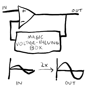
Say we want an amplifier that will double the volume of our audio. We have a circuit that wants to satisfy V+ = V-, and we know theoretically we can force Vout = X(V-) for some controllable value of X, by jamming components into the feedback path. If we set X to 0.5 - i.e. future V- is always half the value of Vout - then at the point where V+ = V-, Vout will be double the value of V+. We’ve forced it to satisfy both V+ = V- and Vout = 2 * V- simultaneously, whilst running in an infinite loop where future V- is constantly set to half of Vout.
So for V+ = 5, for example, when the circuit stabilises at V- = 5, Vout is 10.
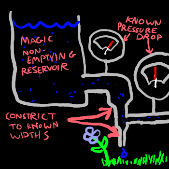
What’s inside our magic voltage-halving box? Think of the hydraulic analogy again: if we have water flowing at a given rate through a pipe, and we want to lower the water pressure, then we widen the pipe. Or, getting creative: we create a T-junction, and allow some of the water to bleed off to ground through a narrow pipe. By controlling the width of the initial pipe flowing into the T-junction, and the width of the bleed-off pipe, we can control what proportion of the original water pressure will make it through the junction, regardless of flow rate.
How do we build such a thing electronically? As mentioned earlier, in the hydraulic analogy, our electronic “pipe narrowers” are resistors, and a pair of resistors in this kind of configuration - one in series with our load, one in parallel with ground/the path back to the opposite supply terminal - forms a voltage divider.
By dividing the voltage by 2 along the feedback path, we force V- to always be half of Vout; so when the op-amp stabilises at V+ = V-, Vout = 2 * Vin.
Again, there is no magical free energy here: the additional voltage is pulled from the op-amp’s power supply, and the output can’t swing higher or lower than the supply rails. (Exactly how close it will get varies across models of op-amp.)
The equations in the voltage divider calculator linked above aren’t quite what we want when used in this configuration, because maths. The good news is the gain equation for a non-inverting amplifier actually ends up being even simpler.
Building Block the Second: Non-Inverting Amplifiers
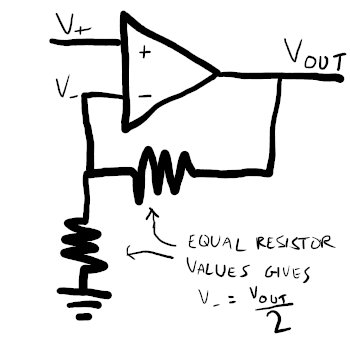
This is our second re-usable building block: a non-inverting amplifier (the signal isn’t flipped upside down), with a fixed gain (the amount the signal is multiplied by) set by a voltage divider in the feedback path.
In fact, voltage dividers kind of qualify as a bonus building block in and of themselves; but here, they’re just a means to an end: by controlling the ratio of V- to Vout, we in turn control the ratio of V+ - our input signal - to Vout.
TL07x Rules of Thumb
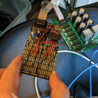
In the real world, two very-commonly used models of op-amp in Eurorack modules are the TL072CP and TL074CN. These are incredibly cheap, well-stocked op-amp chips; the TL072CP contains 2 op-amps, and the TL074CN contains 4, and in both cases a single pair of power pins drives all the op-amps inside the chip.
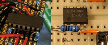
- They can happily accept ±12V on their power pins
- Their “common mode” operation - i.e. the range in which they operate as
expected, without weird quirks like suddenly swinging the output all the way
to the opposite rail - expects the following rules to be obeyed:
- At least 4.5V difference between positive and negative power pins
- Input voltage not below Vs- + 4V. So when Vs- = -12V, don’t use inputs lower than -8V.
- Input voltage not above Vs+ + 0.1V.
- In complex circuits, and/or if the traces between the power supply and power
pins are large, place 0.1µF capacitors close to the power pins; one leg on
the power rail, the other going to ground.
- These form low-pass filters, removing any high-frequency noise on the power rails, giving stable supply voltages and reducing noise in the chip’s operation.
- If you have the space and the parts, these are generally considered mandatory. I haven’t put them in this particular level booster partly because I was being lazy, and partly because the op-amp chip is literally the only thing in the circuit after the power conditioning, so I figured it would already be pretty noise-free. It seems to be Good Enough for my purposes.
- Don’t short the outputs to ground.
- I haven’t mentioned Ohm’s law yet, but we’ll see it again later: V = IR, where V is voltage, I is current, and R is resistance. To continue supplying a constant voltage, if resistance drops, current goes up, and it’s usually high currents that heat things up and release the magic smoke! If an op-amp is trying to supply 10V directly to ground, via a bare length of wire, current will go up, heat will go up, and chip will go bang.
- Strictly speaking, the Texas Instruments TL072CPs and TL074CNs I and many others use include current-limiting resistors on their output pins, internal to the chips themselves, to stop too much current flowing in a short-circuit scenario: they’ll get warm, and be more power-hungry than they could be, but shouldn’t damage themselves.
- However, to be extra sure - and because outputs are always momentarily shorted to ground when plugging patch cables in, and because we might be connecting the output to a poorly-designed, power-hungry module that doesn’t use an input buffer, preferring to draw current directly from its input signal - it’s good practice to add your own additional 1K current-limiting resistors in between the output pins and jack sockets.
- When picking resistor values for gain setting, the final gain is determined
by how the resistors relate to each other;
so in theory, a pair of 10Ω resistors, a pair of 100Ω resistors, or a pair of
1KΩ resistors will all give you a gain of 2. So which should you choose?
- Prefer resistors in the KΩ range. Again, this comes back to Ohm’s law; we know the voltages we’re working are in the single-digit/low-double-digit figures, and the chips expect currents in the milliamp range, so to line everything up we want resistances in the kilo-ohm range. If our resistances are orders of magnitude out, then our currents will also be orders of magnitude out, if we demand that the chip output the same voltages.
- In fact, the data sheet for the TI parts literally states, “Selecting a value in the kilohm range is desirable because the amplifier circuit uses currents in the milliamp range. This ensures the part does not draw too much current.”
- Don’t leave unconnected inputs floating.
- In a non-inverting amplifier like the above, one input is always used, as it’s connected to the feedback loop; but the other input should always be connected to either signal or ground, not just left disconnected. Left disconnected, it’ll be picking up random noisy voltages from any passing interference, and constantly trying to amplify them, instead of sat there happily outputting 0.
- The design of 3.5mm jack sockets helps with this: they can easily be wired
up such that when no jack is inserted, the signal pin makes contact with
a “normal” pin; simply solder the normal pin & ground pin together to
ground.
- Only do this on your input jacks, not output jacks! For inputs, you want them connected to ground when nothing is connected; for outputs, this just means any unconnected output jacks become a short to ground, which as discussed, is bad. The outputs don’t have any problem with “floating” in the same way as the inputs do, because their values are actively driven by the amp. I initially did short the normal & ground pins of my output jacks, and can confirm that the op-amp IC got uncomfortably warm in operation, and the problem went away after de-soldering these connections.
I leave it as an exercise for the reader to divine the rules of thumb above from TI’s official datasheet. It’s dense and obtuse, but it’s all in there, if you know where to look; and lots more besides.
Coming back to Eurorack’s artisanal jank: given that these particular models of op-amp are cheap as chips (pun not intended), happily accept ±12V, and will very happily output Eurorack signal levels (0..8V for envelopes, -2.5..+2.5V or -5..+5V for control voltage, 0..8V for pitch, -5V..+5V for audio, etc.), I suspect that the overlap between the price and these design parameters is not an accident. Even the physical form factors are a good fit, as they’re available in rectangular packages with two rows of nice chonky pins, that can easily be either hand-soldered directly through holes in a PCB, or inserted into a (similarly hand-solderable) socket for easy repairability, or even jammed directly into a breadboard (as long as you make sure the rows of pins are on opposite halves, so you aren’t shorting them all to each other).
Even if Doepfer didn’t specifically have the TL072CP and TL074CN on hand when designing the original modules, they seem like a good starting point for any application other than precision manipulation of control voltage. I am NOT an experienced designer, but I’m tempted to say always try prototyping with them and decide if you need something more expensive later. (More expensive op-amps might allow output voltage to swing closer to the supply rails, or have lower noise floors, or have lower offset voltage - a small non-zero amount always added to the output, etc.)
3.5mm Mono Jack Sockets
These things are essential for actually getting any sound into or out of the amplifier, and very conveniently designed, but every time I look at the symbol for one in a circuit diagram I get very confused.
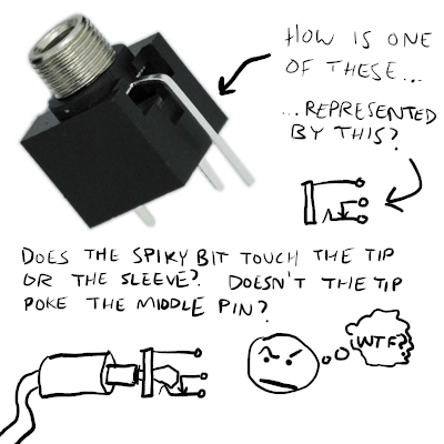
I find it helps to remember that it is not drawn to scale. If it was, the ground ring would be much further away from the ends of the pins, and the pins would be spaced out more like they are on the actual physical socket:
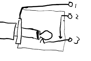
This is of course not what the internal construction looks like, but it helps me get my head around it.
- Pin 1 is the ground ring, which connects to the sleeve/ground plate on the jack connector.
- Pin 2 is the “normal” pin. If you want to have a specific voltage/signal
from elsewhere in your circuit act as a “default input” when no patch cable
is plugged in, connect it here.
- Pins 1 and 2 are - at least, on a Thonkiconn, as pictured above - close enough to easily bridge them with a blob of solder.
- To repeat some of my rules of thumb from earlier, which are definitely
applicable to this amplifier design, and probably pretty broadly applicable
in general:
- You do want to connect pin 2 to ground on your input sockets, to stop the input pins of your buffer/amp/whatever IC from floating and just sending noise into the chip
- You do not want to do this on your output sockets, or you’ll be short-circuiting the output of your last component to ground whenever no cable is plugged in, needlessly consuming power and possibly releasing the magic smoke.
- Pin 3 is the signal pin. When no jack is inserted, it makes contact with pin 2; with a jack inserted, that connection is broken, and it connects to the tip of the jack instead.
To Be Continued
Part 5 - The Final Circuit