DIY Euro-amp Part 5 - The Final Circuit
This article is part of my series on building a Eurorack audio amplifier, to go from line-out on a field recorder or Raspberry Pi to my modular synth rack. To start from the beginning, click here.
This is part of my Memento Potato project, in which I am ostensibly producing my third album and releasing each track as & when it’s done, but also using it as a vehicle for tons of other things I’ve wanted to build/film/explain/code/nerd out about along the way.
Table of Contents
The Final Circuit
The Final Recap
To recap again, because this article series is getting far, far, far too long now:
- We know why our audio is too quiet when we hook up the field recorder/ Raspberry Pi’s line out directly to a Eurorack module input: the voltage levels are not high enough.
- We looked briefly at what electricity is, and clarified jargon such as “ground” and “short”.
- We know that Eurorack power standards are jank, and I would hesitate long and hard (and do lots more research, and prototyping, and poking around on the Modwiggler forums) before ever trying to design a PCB to sell to anyone else; but making DIY stuff for personal use, we can deal with it with a simple, cheap, rail-conditioning & reverse power protection circuit block.
- We kind of know what op-amps do, even if not how they do it; and we know how
to use negative feedback to wangle their high internal gain into something
useful.
- We know how to make an op-amp duplicate its input, and how to use a voltage divider in the feedback path to turn the output into a higher-voltage copy of the input. OPERATIONAL AMPLIFICATION!
- We also looked at the rules of thumb for using two real-world op-amp chips, and satisfied ourselves they work very nicely within our voltage ranges, as well as being very cheap and conveniently packaged for DIY.
- We looked at what jack sockets are, how normalled inputs work, and when you should and should not have them normalled to ground.
- We even remembered to put current-limiting resistors as our last component
before the output jack sockets, even though there are technically already
some built-in to our op-amps, because:
- Patch cables always momentarily short our output to ground whilst the other end is being plugged in, and …
- Just in case we’re plugging it in to a poorly-designed module, that really ought to have an amp/buffer on its inputs (but doesn’t), we don’t want it trying to use our output signal to power itself.
Are we forgetting anything?
Setting the Gain
Way, way back in part 1 (oh how innocent we were back then - was I even talking to you in the second person yet? Inconsistently, you say? Huh), I measured the voltages coming out of my field recorder’s line out at ±0.447V, or 0.894Vpp. Otherwise known as “consumer line level”.
Let’s aim to get as close as we can to ±5V, shall we?
By vaguely remembering that we want to pick resistors in the kilo-ohm range, looking in the component drawers to see what values of cheap resistor we have on hand, and jamming numbers into our handy voltage-divider calculator until we get what we want, we can get to the following:
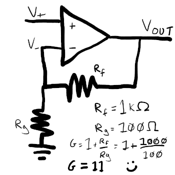
- A voltage divider with an Rf (feedback resistor) of 1KΩ, and an Rg (ground resistor) of 100Ω, will divide the op-amp’s output voltage by 11 before feeding it back into V-
- From our intuitive understanding of non-inverting amplifiers, we know that if V- starts out 11 times smaller than V+, then it will stabilise at the point where Vout is 11 times larger than V+
- 0.447 * 11 = 4.917, which is close enough for us without resorting to weird, specialised, expensive resistor values
Or, if we actually remembered that there’s a simpler gain equation for non-inverting amplifiers, and bothered following our own links, we could have jumped straight to G = 1 + Rf/Rg = 1 + 1000/100 = 11. But we didn’t do that, because we’re idiots, and instead wasted an hour or two looking at what 0.25W resistor values are cheap on CPC and plugging numbers the wrong stupid form.
Bill of Materials
- One notched, 10 pin, 2 row, 2.54mm pitch pin header, for the power cable
- Two 1N5817 or 1N5819 Schottky diodes, for reverse power protection
- Two 10Ω resistors, like these cheap 0.25W metal film ones, to form one half of the low-pass power rail noise filters
- Two 0.1µF (100nF) capacitors, like these cheap ceramic ones, to form the other half of the low-pass power rail noise filters
- Two 47µF capacitors, like these cheap electrolytic ones, to smooth out small, temporary voltage dips on the power rails
- One dual-inline, 14 pin, 2.54mm pitch IC socket to house our op-amp chip
- One TL074CN quad operational amplifier chip, the brains of the operation
- One TL072CP dual operational amplifier chip, optional, for starting smaller on a breadboard first
- Four 100Ω resistors, again cheap metal film ones will suffice, to act as Rg in the voltage dividers for our non-inverting amplifiers
- Eight 1KΩ resistors, also cheap metal film; four to act as Rf in our voltage dividers, and four to act as current limiters on our outputs
- Eight 3.5mm mono audio jack sockets, like these Thonkiconns, to plug in our input and output patch cables
- Prototype board of choice, if you actually want to solder this thing up and keep it on something more permanent than a breadboard. I’m using these breakable ones by Electrocookie; they snap into quarters for sizing, have mounting holes in the corners, and the connectors along two edges of each piece are connected into continuous rails, perfect for wiring up as our common ground
Oh, I’m also assuming you have a spare Eurorack PSU you’re happy to use for experimentation; i.e. something not already mounted in a case and hooked up to modules you actually care about. I’m currently using a Frequency Central Microbus as my “bench” supply.
If anyone knows of good options for enclosures/mounts, both for that PSU and for these prototype boards, I would be very interested. At the moment I’m using them as just bare boards, and the potential for some piece of exposed circuit to touch something it shouldn’t is uncomfortably high.
Tools
Just the basics: soldering iron, spools of insulated wire, wire stripper/cutter, soldering mat, PCB holder, multimeter, etc. These breadboard kits with a bunch of different included jumper wire lengths are pretty nice, too.
Only other thing I’d say it’s definitely worth having if you’re getting into synth DIY is an oscilloscope. Doesn’t have to be anything fancy; basically, anything that can show voltage changes faster than an oscilloscope display will capture is enough to get going. I picked up one of these cheap handheld 5012H scopes, which seem to be a generic model rebadged by countless Chinese brands. It does the job, but I’m considering nabbing a Korg NTS-2; it may be less convenient for poking around on PCBs, but it looks perfect for hooking up directly to patch cables for a visual reference when noodling around with sound design, and does a few other useful synth-specific things in Euro-friendly voltage ranges.
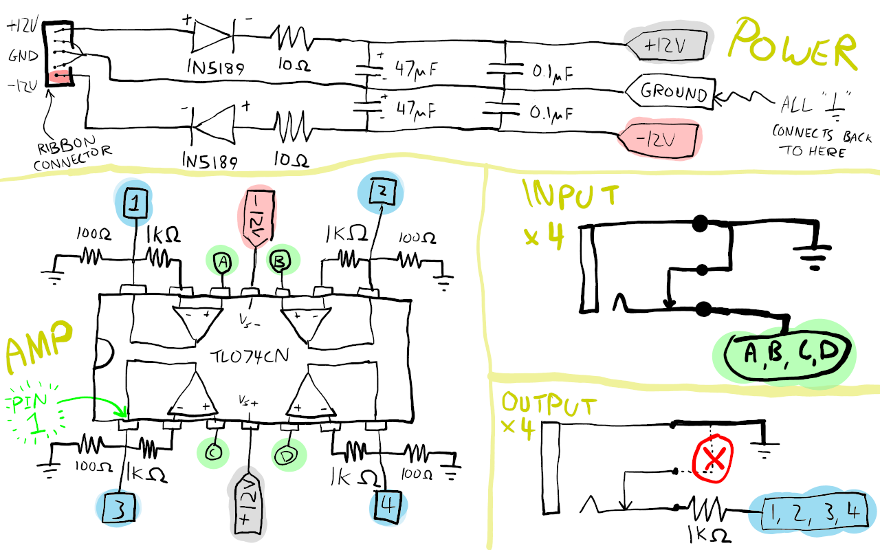
Diagram
- Take care when soldering polarised components:
- The two power-protection diodes have to be fitted the right way round. There should be a silver stripe on one end of the body; this is the negative terminal.
- The two 47µF capacitors are also polarised. The negative terminal usually has a shorter leg attached; also, there should be a vertical stripe on the body closest to that leg.
- In both cases I’ve labelled the terminals on the diagram for clarity.
- Also, make sure you get the TL074CN the right way round: there should be a semicircular notch in the casing on one side, and/or a circle in the same corner as pin 1.
- It’s not too uncommon to see a single circuit diagram broken into sections.
Typically one like this would probably only normally be broken into two,
maybe three; the power section, a section showing how the chip hooks up to
power (but only how it hooks up to power), and a section showing everything
else, leaving you to match up the four op-amp symbols to the physical pins on
the chip. I’ve chosen to focus on the innards of the chip purely because I
think it’s easier for a total noob like myself, just be aware this isn’t how
it’s usually done.
- Circuit diagrams are just electrical diagrams: they show which component is which and how they connect to each other, but are not physical layout suggestions.
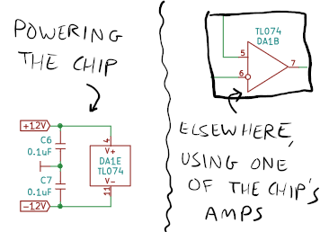
Elsewhere…
For the sake of completeness, this is the kind of thing I’m talking about when stating that other circuit diagrams may be less explicit about the relationship between how chips are powered, and how they are used. Taken from the mki x es.EDU VCO build guide; I don’t know what the license on that is, but I think using it for this kind of educational purpose is certainly within the spirit of things.
Breadboarding
Before soldering the circuit up permanently, if you’re as inexperienced as I am, it might be a good idea to make it up on a breadboard and make sure you can get the smaller two-channel version working first. Here’s a couple of photos showing my own somewhat lacklustre attempts at this.
Bear in mind the pin-out of a TL072CP is obviously different to the larger TL074CN.
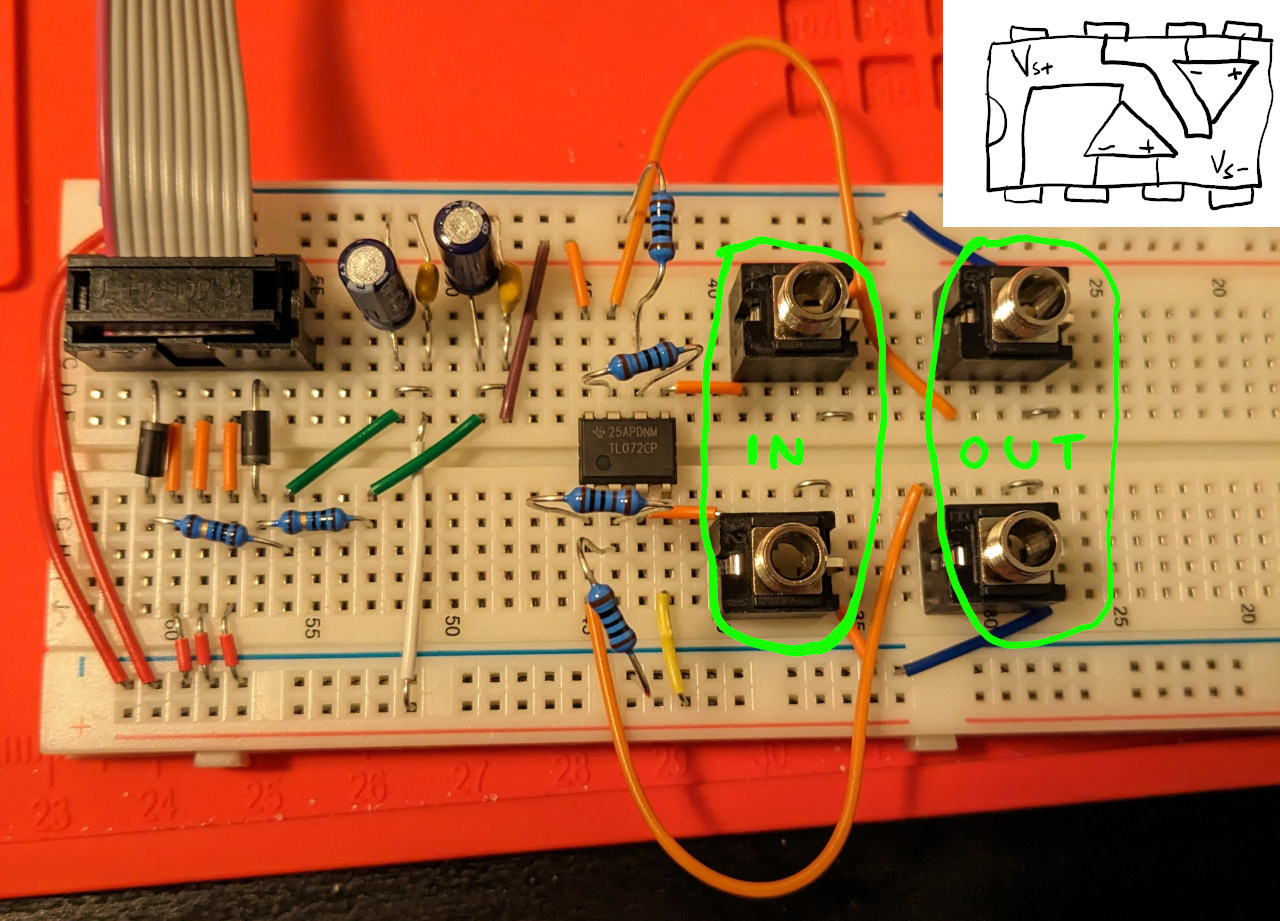
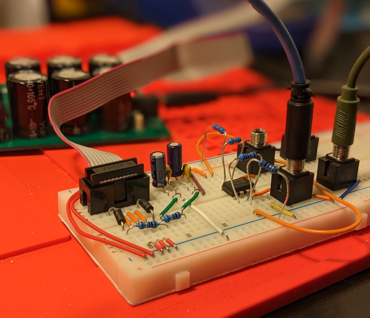
(Also, spot the mistake! Yes, there are little jumper wires bridging the “normal” pins and ground pins on both the input and output jacks; I didn’t notice the two-amp chip getting warm on the breadboard, but once again, don’t do this. Only do this on the input jacks.)
Moving to Prototype Board
I managed to fit it into two squares of the Electrocookie prototype board. A few notes:
- Just solder all the ground pins together, up to the top rail, then use lengths of wire to connect that to any other rails near components that need a ground connection. This isn’t a complex enough circuit to worry about doing anything more fancy with ground, and only needs a single common ground, no 0V reference.
- Double-check the orientation of the ribbon cable socket. You don’t want to solder up the whole thing including power protection only to find you’re connecting it backwards anyway because the socket’s backwards.
- Through-hole components have much longer legs than you usually need. These particular prototype boards have the holes connected to each other in little vertical runs of three; I see nothing wrong with weaving component legs out of one hole and back through another to bridge adjacent runs, instead of wasting time cutting & stripping lots of tiny little jumper wires.
- I don’t have a 3D printer, or any metalworking tools, or even a decent drill; but regardless, I’ve still put all the components on the opposite side of the board to the jack sockets (and diodes, just because of how things got squeezed in). So in theory if I find a suitable enclosure and something to make a panel out of, I could mount a front panel on the jack side easily.
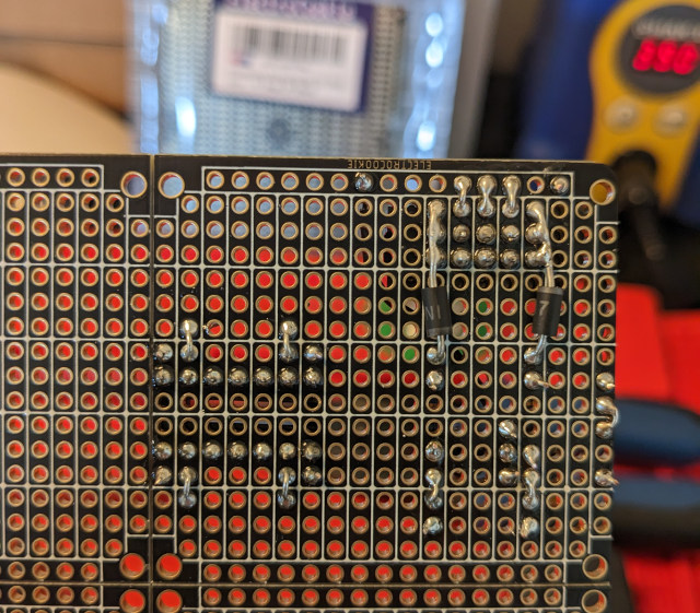
Mounting the power protection diodes on the back, so as to squeeze the power conditioning into the smallest space I could:
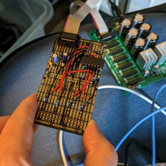
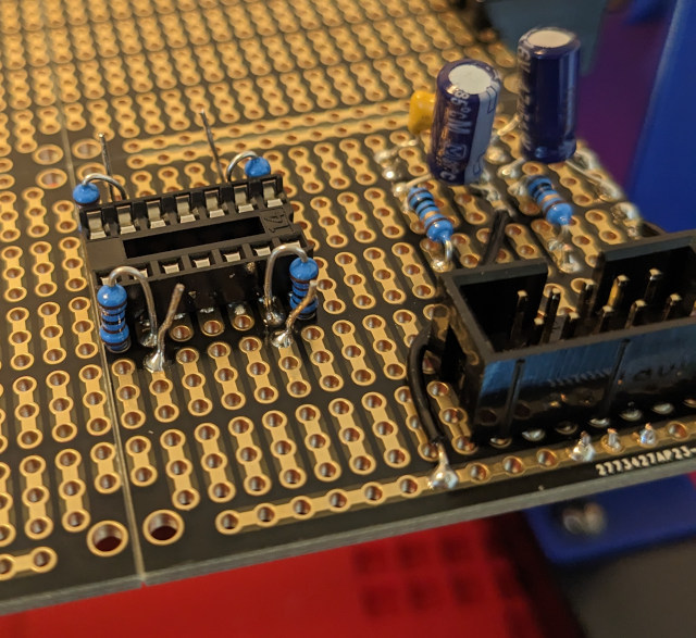
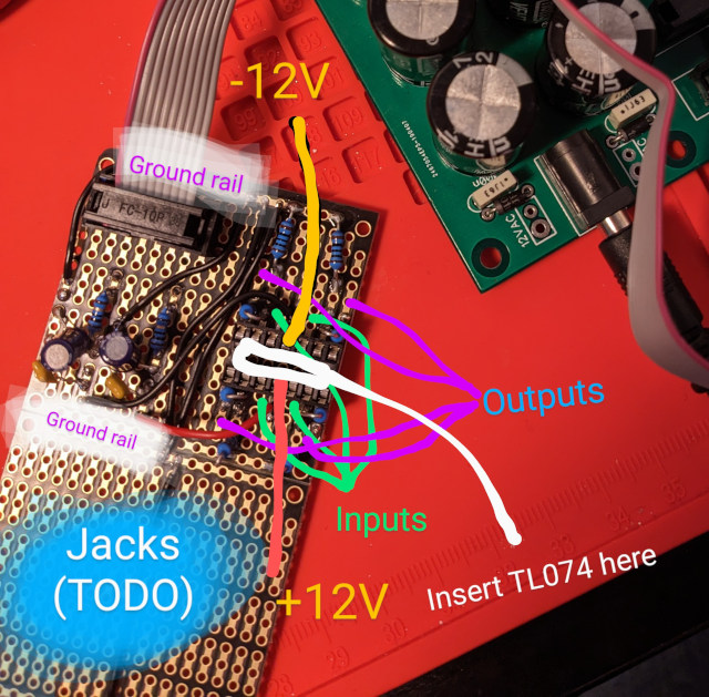
The ribbon cable connector, power capacitors, and socket for the TL074CN. You can also see the vertically-mounted feedback resistors that will loop the output pins pack to the inverting inputs, their not-yet-snipped legs sticking back up through the component side of the board. These have been weaved in & out to connect to both the inverting input pins, and the next run of holes, ready to add the resistors to ground that will form the second half of the four voltage dividers:
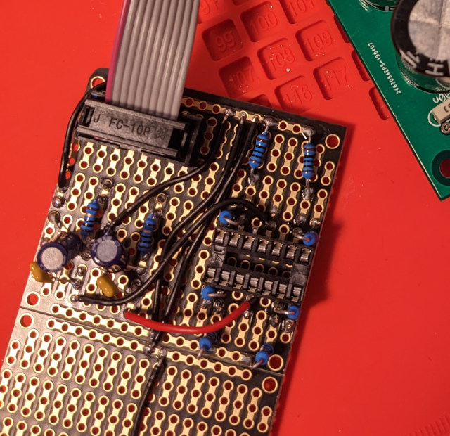
The completed power & amp portion of the circuit, minus the input/output jacks, TL074 not yet fitted:
Last but not least, the whole thing, front and back:
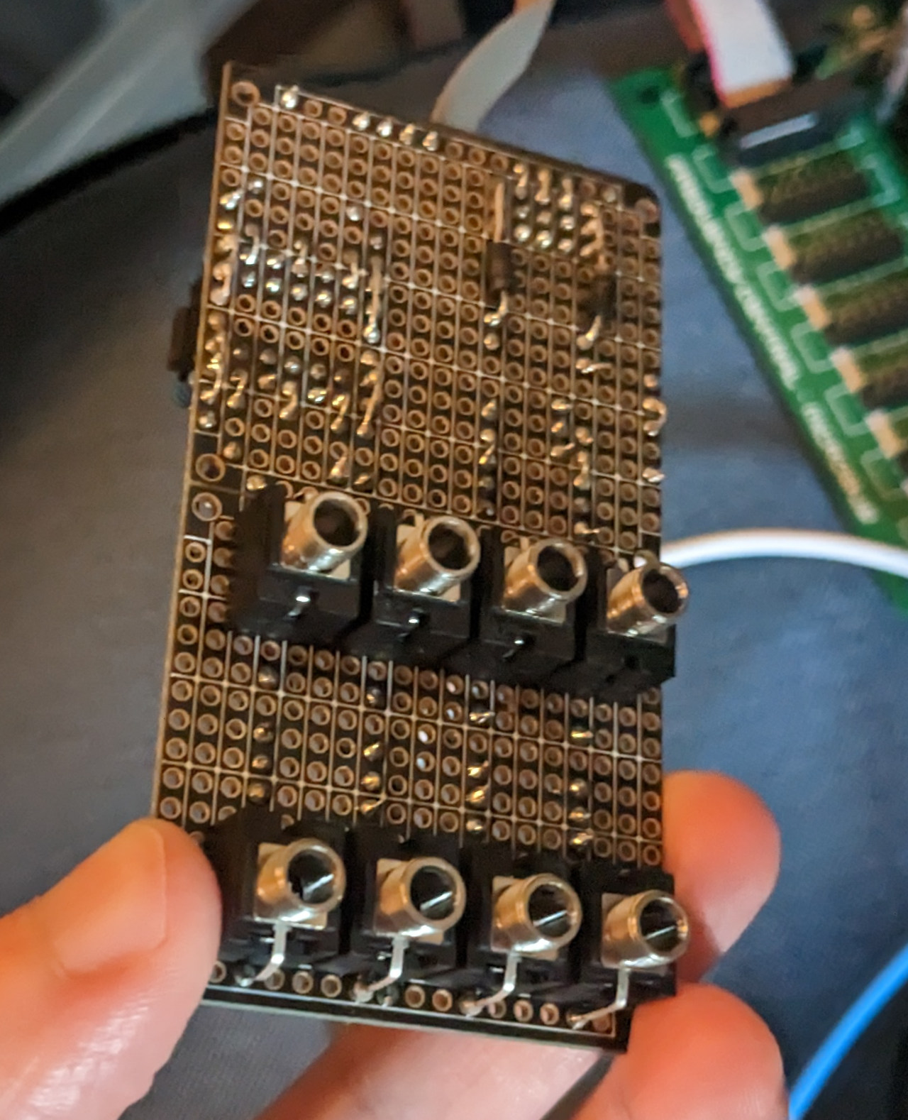
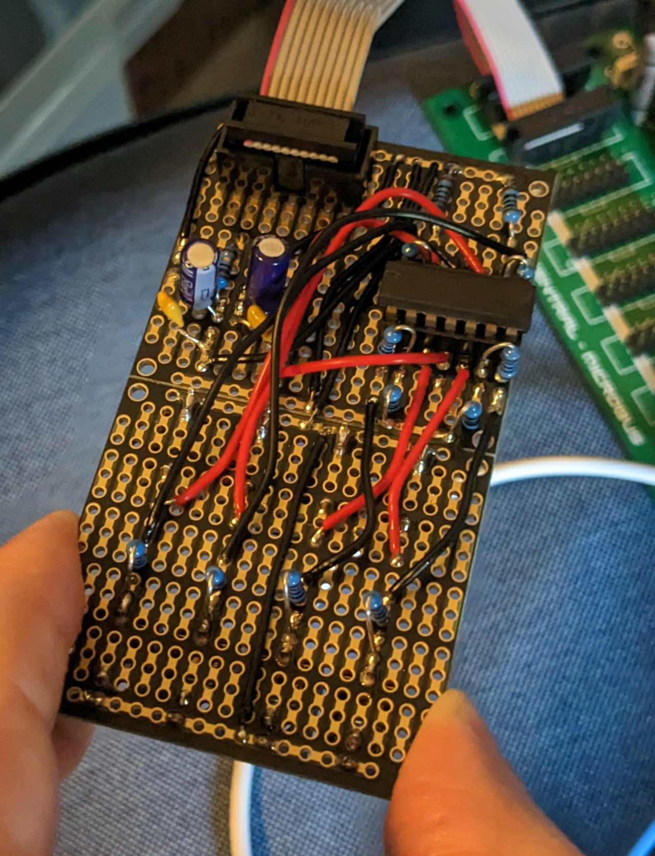
(If you look closely at the bottom of that last one, you’ll see the solder blobs on the bottom ground rail look a little scorched; that’s from where I initially soldered them to the “normal” pins just above, then undid that after I noticed the chip getting toasty and realised my mistake.)
In Conclusion
Electronics is not magic; by lowering your expectations, swallowing your fear and pride, and being OK with learning a bunch of building blocks & rules of thumb that far cleverer people already figured out before you got there, you can go far.
Well.. you can get your foot in the door, at any rate.
The most obvious improvements to this thing would be:
- Beefing up the power conditioning, using actual voltage regulators to derive our own reference voltages inside the module, rather than relying on stable ±12V supply rails. If I was actually going to get a proper PCB and panel made up, and put it into a case with modules worth actual money, I think this would become worth the cost (and research, because I’ve never used one).
- Replace the fixed-value Rf resistors with 10K potentiometers
- Potentiometers are basically variable-value resistors, going from 0 up to their rating, set by turning a knob. 10K would give us our original behaviour when turned fully clockwise, but give us the ability to turn the volume down.
- A 50K pot (the next value up I can see cheaply available) would let us turn the volume up as well as down, but then I’d need a bunch of extra parts and would have to figure out how clipping works, and also pick a higher value for Rg, otherwise fully clockwise we’d have a gain of 501(!!) and I don’t think the op-amp would take kindly to having 224V shoved into it.
This series was originally meant to be one article, and just be an introduction to op-amps, then dive straight into the final circuit. But because this is literally the first time I’ve done anything like this, and I haven’t had any electronics training, I wanted to try and capture everything I learned along the way. If this helps at least one person get into synth DIY, in less time than it took me to unpick the web of assumptions, jargon, and prior knowledge that got me to the stage of actually building something without working purely to someone else’s design, then it will have served its purpose.
All the Calculators
Because other people have already done the maths, so we can just plug in numbers for the components we have until something looks right.
Fin
I think I’m off to snap off a square of prototype board and solder another one of those vintage power conditioners, with pin headers for detachable jumper wires, because they’re as good as I need at the moment, and I’m sick of breadboarding them from scratch.
Peace out.