DIY Euro-amp Part 3 - The Hydraulic Analogy
This article is part of my series on building a Eurorack audio amplifier, to go from line-out on a field recorder or Raspberry Pi to my modular synth rack. To start from the beginning, click here.
This is part of my Memento Potato project, in which I am ostensibly producing my third album and releasing each track as & when it’s done, but also using it as a vehicle for tons of other things I’ve wanted to build/film/explain/code/nerd out about along the way.
Table of Contents
The Electrons Must Flow
Let’s take a step back. What even is electricity? Electrons flow through wires, energy is transferred. Or do they? Maybe they do, but only on the outer surface of wires. Maybe they do but really really slowly, but somehow this doesn’t stop the field generated outside the wire from moving really really fast, and it’s the field that does most of the work anyway.
(If you aren’t familiar with Veritasium and ElectroBOOM on YouTube, I highly recommend this set of videos going back & forth over exactly that sort of stuff. Turns out none of this is obvious even to people far, far cleverer than I.)
Why does current flow from negative to positive when surely the other way round would make a ton more sense? Historical accident.
The Hydraulic Analogy
One equation-free, intuitive way to think about three of the four types of component we’re going to use is the hydraulic analogy. In this way of looking at things, wires are like pipes, and electrons are like a fluid inside those pipes.
- Voltage can be thought of as pressure.
- Current becomes a measure of flow rate.
- Resistors are like narrow pipes; they restrict the rate of flow through them.
- Diodes are one-way valves.
- Capacitors are like a kind of rubber sheet stretched across the inside of a
pipe (with fluid on both sides): pumping fluid in one side will stretch the
sheet, and push fluid out of the other side. However, since no fluid can
actually flow through the sheet, once it’s fully stretched out under pressure,
it can’t push any more fluid out.
- The end result is changes in pressure on one side get transmitted to the other, but a constant, unchanging pressure will generate no flow on the other (the sheet is stretched out, but not actively pushing/pulling any fluid once it stops stretching any further).
- A battery is like a kind of constant-pressure
pump: it will pump electron fluid out from its negative terminal, and
suck fluid in to its positive terminal, with flow regulated to maintain a
constant difference in pressure between the two terminals.
- If you short the terminals, it’s like hooking the pump’s inlet & outlet with a small loop of pipe; fluid will flow at a constant rate in a circle.
- Disconnecting a battery is like blocking the inlet & outlet: the pump will push until the fluid is pressing on the outlet cap at the rated pressure, then stop. In fact, all pipes in this analogy are implicitly capped when disconnected.
- Earth is like the ocean, or a huge lake: you can pump fluid into it, and suck
fluid out of it, but there’s so much of it that you won’t ever be able to
drain it or over-fill it, and it’s open to the air so you can’t pressurise it.
- A balloon charged with static is like a sealed, pressurised container. Touching it opens the valve on a pipe between the container and the lake, and fluid will be pushed out until the pressure level equalises.
High-Pass Filters
As mentioned earlier, capacitors effectively transmit changes in pressure; but once pressure stops changing on the input, and the membrane has already expanded and displaced all the excess fluid through the output, nothing will flow & the output pressure goes back to being neutral. In electrical terms, this means capacitors “block” constant voltage: applying a changing voltage to one leg of a capacitor will produce the same changing voltage on the other leg; but if you apply a constant voltage to one leg, then on the other leg, you’ll get a brief spike in voltage, then it will drop to zero.
The more rapidly the input voltage changes, the more closely the output will match it; slower changes will provoke smaller and smaller relative changes on the output. It blocks low frequencies. It’s a high-pass filter! Add a resistor in parallel with the output, to allow the capacitor to “leak” at a known rate, and you can control the frequency at which the “blocking” kicks in.
I know, I’ve drawn the “capacitor” as some kind of weird water/air leaky container, rather than a stretchy membrane; this is wrong, but correct enough for the purpose of getting an intuitive understanding. I drew it before fully understanding the balloon/stretched-membrane analogy, with the thinking being that water & hydraulic fluid aren’t compressible, but air is, so maybe some kind of mixed water-with-a-bubble-of-air thing might work? In reality this would still allow current (water) to flow even once fully charged (air bubble squished into its smallest), which IIUC a real capacitor wouldn’t; but given the resistor to ground allows it to constantly slowly discharge, it’s Good Enough. I think a more correct visualisation of a capacitor would be a bit like this:
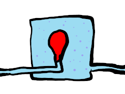
So the balloon can expand & contract, pushing water out & sucking it back in respectively; but apply a constant, unchanging pressure to one end, and the other end will stop flowing once the balloon has settled. (Even that seems not quite right to me, because I think current can flow through a capacitor, as long as it is able to keep charging and discharging? Something about a thing called displacement current, which I don’t understand and hence can’t wangle into my intuitive model, so won’t try to cover.)
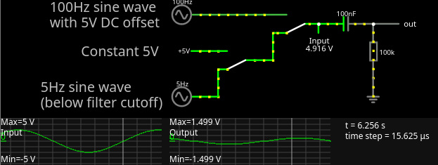
In practical terms, this could be a literal musical high-pass filter (to remove bass), a power conditioning filter to smooth out slow fluctuations in supply, or - perhaps least intuitively, but very usefully for circuit design - something to “re-centre” a signal around 0V, removing any constant offset. Coming back to this picture:
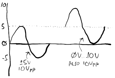
Running the signal on the right through a high-pass filter will give us the signal on the left, as it filters out the 5V, “zero hertz” frequency component.
This kind of filter is called an RC filter (resistor/capacitor filter). Used for electrical rather than musical purposes, a circuit with its input filtered like this is said to be A/C coupled (only sees the “alternating” part of an alternating current); circuits that preserve constant offsets are, respectively, said to be D/C coupled.
Side note: if you were to flip the positions of the capacitor and resistor in this arrangement, you get a low-pass filter.
A More Concise Explanation for Filters
Another way to think of it is like this: capacitors are like a special kind of resistor, where the resistance goes down as the frequency of input voltage changes goes up. So to make a high pass filter, put the capacitor in series (and the resistor in parallel), to restrict the passage of low frequencies. To make a low pass filter, put the capacitor in parallel (and the resistor in series); low frequencies will “see” a high-value resistor to ground and pass through to the rest of the circuit, whereas high frequencies will see a low-value resistor, and take the shortcut.
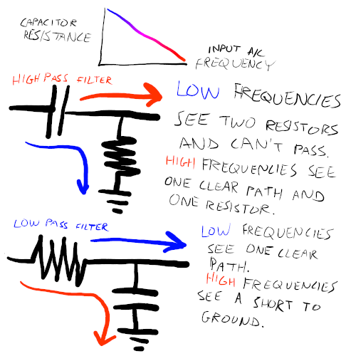
Please note, I don’t actually know that the resistance/frequency relationship is linear, as implied there, and resistance can’t literally drop to zero in the real world. It’s just to illustrate the concept.
This alternative way of thinking about capacitors - as something that presents as a resistor to low frequencies, and a bare wire to high frequencies - also helped me intuitively understand why you’ll sometimes see people doing things like soldering a capacitor so that it connects both power pins of a chip: low frequencies (the 0Hz, whatever-voltage DC power supply you want) will see it as a resistor and prefer to go through the chip; high-frequency noise will see it as a shortcut, and jump straight over to the other supply terminal.
Interactive Demo
Go and play with CircuitJS. It’s fun.
Building Block the First: Eurorack Power Conditioning for Beginners
We now have everything we need to create our first useful thing: a reusable arrangement of diodes, resistors, and capacitors that can alleviate the jank of Eurorack’s power arrangements, giving us clean, stable ±12V rails and protection against plugging in ribbon cables the wrong way round.
The resistors & small capacitors will filter out high-frequency fluctuations, such as you might get if there’s a digital module sat somewhere in the same rack with a high-frequency clock oscillating away noisily, or radio frequency interference. The big capacitors smooth out temporary dips in supply. The two diodes, one in each direction, ensure the +12V rail won’t become a -12V rail (and vice versa) if a ribbon cable is connected backwards; rather, the module won’t turn on. Also, the resistors will burn out in some other cases of short circuit or malfunction; but that’s a side benefit that might save some fried chips, not their main purpose.
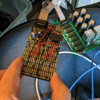
Eurorack-powered Breadboard

The photo here shows that in action in a breadboard; in this layout, the two blue-striped board rails (the stripes on the board, not the stripes I’ve drawn on) are ground, and the two red-striped rails are power - +12V at the top, -12V at the bottom. Maybe not the most compact layout, but it’s what I came up with.
“For Beginners”
I call this “for beginners” because, whilst it’s good enough for prototyping on a breadboard, and good enough if you have a small DIY rack with a handful of basic modules - eliminating any spikes on power-on/power-off, plugging/unplugging patch cables to/from adjacent modules, etc. - it is very much a, umm, vintage design. If you actually wanted to sell something for general use, which buyers might slap into any old case loaded with arbitrary modules from a bunch of different manufacturers, it’s apparently considered bad form to use the supply rails directly as your reference point.
I get away with it here because I’m not going to be shoving this thing into my main case, and it will consume a tiny amount of current which shouldn’t make the PSU bat an eyelid. For something more modern, I’m not really experienced enough to give advice, but I think you’d basically want the module to generate its own internal reference voltages using something like a 78L12/79L12 pair - but those are £0.35 each, compared to £0.99 for a pack of fifty of our trusty 10 ohm resistors.
Anyway, it’s good enough for Erica Synths, who I shamelessly stole it from.
To Be Continued
Part 4 - Op-amps for Noobs